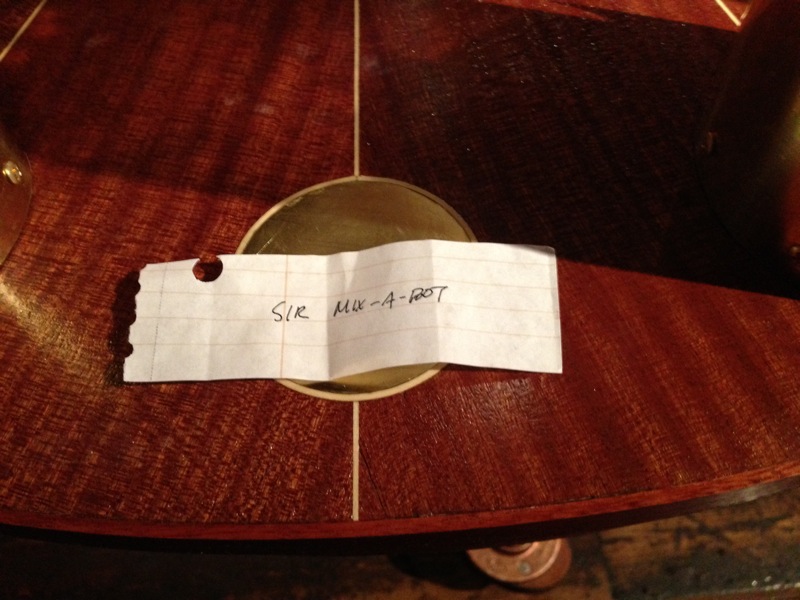
A little over 10 years after I came into possession of it, I turned an old PUMA robot arm into a robot bartender, dubbed by the crowd at its debut Sir Mix-a-Bot.
Read on, or if you like, you can skip to another part of the page to see:
The Story | Mechanical | Electrical | Software | Cabinet Construction | Pictures & Videos | What's Next? | Acknowledgements
The Story
In 2002, I was working at Bluefin Robotics in Cambridge, MA. We had an intern who was a big puppy dog of a kid, and he came bounding in one morning exclaiming "Dave! Dave! They're throwing away robot arms at school! Do you want one?!" After quickly wondering what I'd be getting myself into, I said yes — obviously, who doesn't want a robot arm?
I didn't have a car at the time, and so I convinced my housemate Laura to drive me down to Northeastern, where we filled her hatchback with not only the arm, but a boatload of electronics and junk that came along with — the controller, a teach pendant (sadly long lost), an I/O module, and I can't even remember what else.
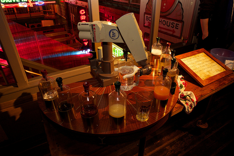
Pretty quickly, I latched onto the idea of making it into a bartender. From the get-go, I had visions of a bunch of bottles within grasp of the arm, allowing it to mix a variety of drinks. I still don't know exactly why this tickles me, but it really does, and I got a huge kick out of seeing it whirling around at my birthday party (where it made its debut).
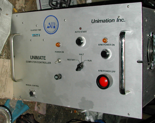
Back in the garage, I sifted through the newly-acquired treasure and was a little sad to discover: it didn't really work. At all. The controller didn't seem to turn on, and even if it had, there was woefully little in the way of documentation of the PDP-11-based computer that was housed in an aluminum box the size of a dorm-room fridge. I kept the control panel cover, the I/O module, the arm of course, and not much else. With a robot arm in an unknown mechanical state and no working controller, I had a tall task in front of me: get the arm repaired, find (or build) electronics to control it, write software to make it pour drinks, and build some sort of home for it.
You have to understand, I do this kind of stuff at work — that is, engineering projects, integrating mechanical and electrical parts with software, build stuff, etc. Obviously, this helps, but it also meant that at the end of a day, I wasn't necessarily eager for more of the same. This resulted in what some might term an absurd overall project length — it took me 10 years to have something I was excited to share with my friends — but I wouldn't have done it any other way (at least without a paycheck and different terms). I worked on it when I was excited to work on it, and it was satisfying and rewarding in all sorts of ways.
Over the course of 10 years and three apartments in two cities on opposite coasts, I picked away at the work, sometimes spending whole weekends on the project, other times not touching it for a couple months straight. Often, visits from my brother would prompt a flurry of action, other times it was a note from a friend asking how the project was going. And then towards the end, the pace picked up after I announced that 2013 was the year of the robot bartender (and I meant it, this time!) — nothing like a deadline to get things going!
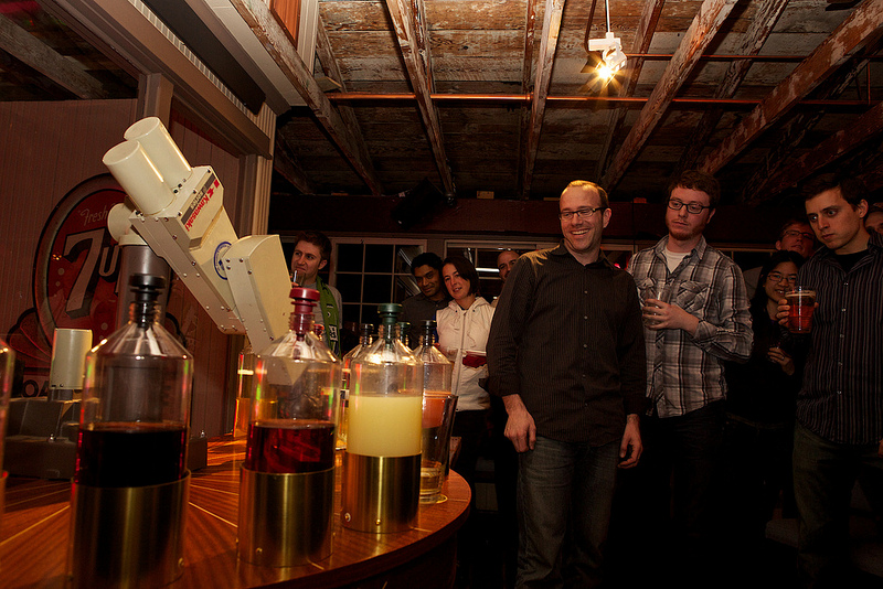
The bartender made its debut at my annual Pi(e) Party in March 2013 (I was born on Pi Day), and we asked people to submit names. The short list was impressive (with R2DUI, Arm and Hammered, and R2 Beer Me making the decision a little bit tricky), but Sir Mix-a-Bot was the clear crowd favorite, and so it is named.
(There was another page here before, that chronicled the development in a different way. If you miss that one, you can still visit it here.)
Mechanical
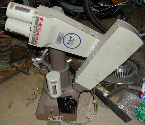
Ironically, the part of this whole project that needed the least attention was the mechanical assembly of the arm itself. It's pretty well sealed up, and whatever grease they used on the gears didn't harden up at all. In some ways, this was a downer, because as a mechanical engineer, this is what I would have been best at. But, it also meant there were more opportunities to learn (than, say, if the electronics and software had been ready to go), and learn I did.
I've taken the arm apart to varying degrees over the years, to explore, to try to count teeth on gears, to temporarily extract motors for testing, etc. But ultimately, the construction is solid, and nothing really needed to be done on the inside.
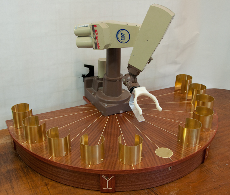
The one mechanical part that did need some attention was the hand. When I got the arm, it was effectively lopped off at the wrist — there was no end effector. I considered quite a few options for how to grab the bottles, and settled on a completely passive setup (that is, there are no motors or solenoids in the hand). I chose plastic bottles because they are compliant (especially in the middle), so the "gripper" could slide around them, and it includes a metal piece that slides underneath and supports the bottles from below:
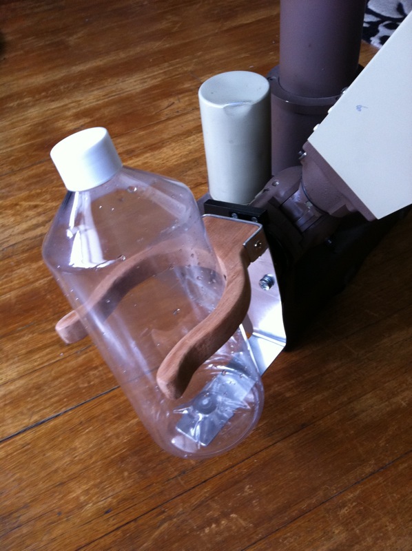
Of course this also required some design work on the fixtures that hold the bottles. More on that later. After proving out the gripper design with the wood prototype, I modeled it up in CAD and called in a 3D printing favor to get a more durable plastic version made. Mechanically (except for the cabinet and bottle holders) I was ready to go!
Electrical
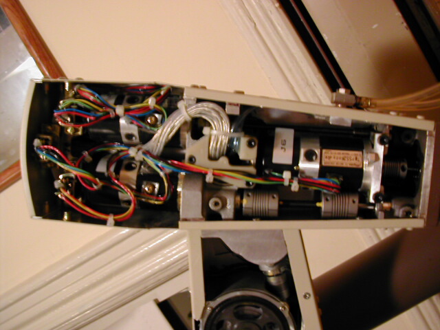
Each of the 6 joints is connected to a brushed DC motor. The first three are driven by larger motors, the last three (the wrist) are much smaller, and all the motors have high-quality glass disc encoders on the motor axle (rather than at the joint), so there is quite a bit of resolution about the joint position.
The three large motors also have electromechanical brakes. These are solenoids that engage or disengage a brake pad (some kind of friction clutch), and these allow the robot arm to support its own weight without continuously using a lot of power to hold the motors in a fixed position.
The first thing I tried was taking one of the smaller motors out of the arm and seeing if I could read the encoder signals; turns out they're fairly straightforward quadrature encoders. Provide +5V input and there are 3 signals output, two pulse trains (A & B) and an index pulse that ticks once per revolution.
Driving a DC motor and handling quadrature encoder signals isn't a new thing; lots of people have tackled this task before, and I wasn't above leveraging some of that work. This page at SeattleRobotics.org does a great job explaining how to use D flip-flops to decode quadrature encoding.
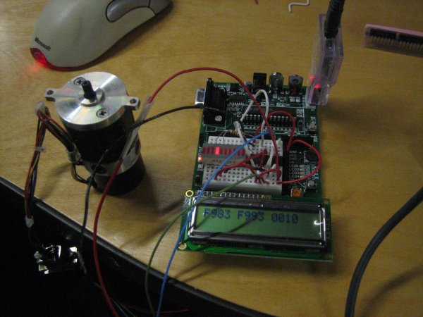
So I started down the path of using a microprocessor (first a PIC, later a PSoC) to read the position of the motors and send a signal to a motor driver chip (LM18200) to actually send current to the motor to make it go, and I got a breadboard system more or less working. Perhaps prematurely, I began laying out a circuit board with all those components on it, one group per joint in the motor. The vision here was that there would be a separate computer (a Mac Mini, or something like that) controlling all the joints.
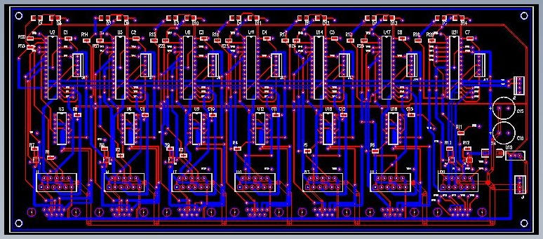
I actually went as far as having boards made, and then proceeded to solder all the components down. To make a long story short (you can read about some of the details on the original page), I ran into a few different stumbling blocks, including some issues with decoupling capacitors (I later found this helpful website), some kind of issue where power wasn't effectively being transferred to the motors, as well as some limitations that stemmed from sending the circuit board off to be made before I really know everything that was going to go on it.
Ultimately, I think I could have done a new board layout and been successful making my own electrical system, but I'm not an electrical engineer at all, and I think it would have both taken too long to finish and not been the most satisfying time. Maybe later?
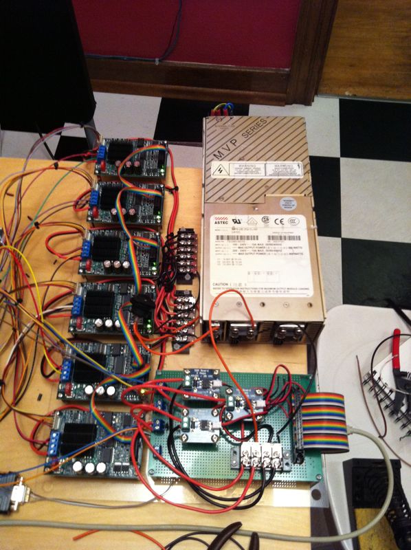
Of course that wasn't the end of the project — I opted to use a combination of off-the-shelf hardware instead of using my own board. After some searching around, I landed on the Motion Mind 3. It handles quadrature encoders no problem, can drive larger motors (24V / up to 9A), and has a built in PID controller. I could connect to the board via USB (thru a USB-to-RS232 converter), and they can also be daisy-chained so I didn't need a ton of USB ports, helpful since I would need one board per motor/joint. I ordered one, got it working, and then ordered 5 more.
I also needed a power supply, ideally one that could supply a variety of voltages — the motors run at 12V, the solenoid brakes need 24V, and at the time I was buying it, I thought I also might need 5V for something. I found a bounty of Astec power supplies on eBay; they have a series of interchangeable modules that can provide a variety of voltages and currents.
I also needed a way to control the solenoid brakes, and this required two things: a way to send a signal from the controlling computer, and a way to turn that signal into the appropriate voltage. Because I had originally planned on communicating with the microcontrollers via I2C, I already had a USB-to-I2C converter board, and it has a handful of general purpose I/O pins — these serve as the signals to the solenoid brakes. Although I could have made my own load switches (to turn those 5V, low current signals into 24V, higher current supplies for the solenoids), I opted to buy 3 of these.
Here's a snapshot of the different components that ended up in the final build:
And here's how everything wound up arranged inside the final cabinet:
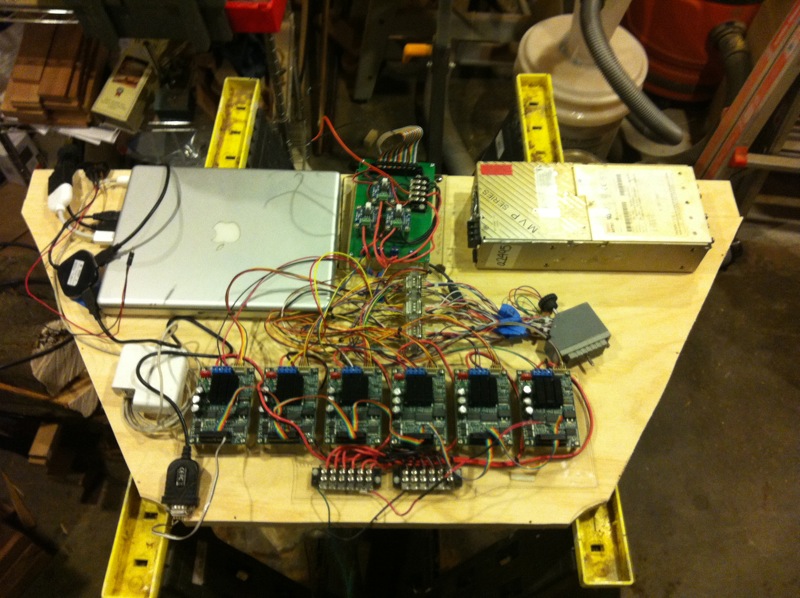
You might notice the Apple power supply doesn't have a plug in that photo. I ended up chopping the plug off and soldering the wires directly to the power receptacle on the input plate. The switch on that receptacle controls the AC input to the large power supply, but the laptop power supply is always on. You can also see the USB and video connections from the MacBook, and the extremely large connector in the middle that is the wiring harness to the arm itself.
Software
The individual motor driver boards do a great job of keeping track of where each joint is, positionally. But they don't talk to each other, and they don't control the large motors' brakes, and so I'm using another computer, my old MacBook Pro, to continually tell each of those controllers where a given joint should be at any given time.
I wrote a set of classes and functions (in C++) to communicate, via the USB-to-serial converter, with the motor controllers, including setting the controller parameters (PID constants and such).
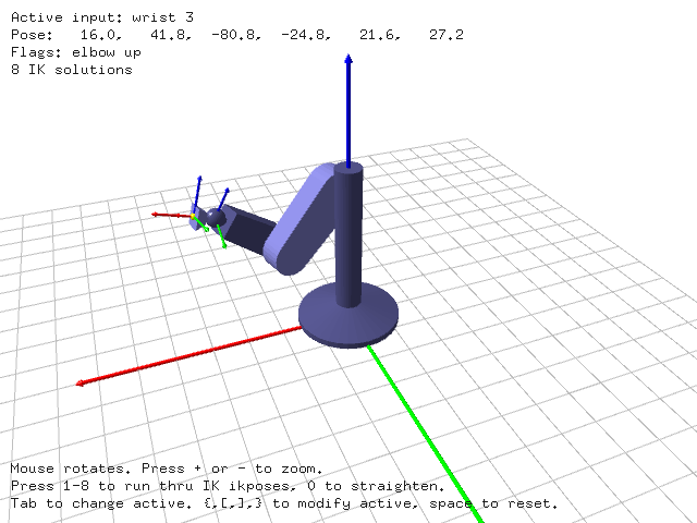
The motor controllers live (effectively) in joint space — that is, they are directly controlling the angles of each of the joints. But sometimes it's helpful to talk about Cartesian space, in terms of (X, Y, Z) coordinates and rotations — for example, you want the end-effector to move up by 15 cm. That requires moving more than one joint, just like in your own arm, moving your hand straight up from waist level to shoulder height requires that you adjust your shoulder, elbow and wrist.
The translation from joint space to Cartesian space is called forward kinematics, and it's a relatively easy calculation — it involves the joint angles, the lengths of the arm segments between joints, and trigonometry. But the translation the other way — inverse kinematics — is much more difficult. Sometimes, there are multiple configurations that yield the same resulting position and orientation. Sometimes, there are no valid configurations. And so on.
This is where having a brother in a PhD program in robotics (at the time) was a real boon. Matt actually had a homework assignment at some point to write the inverse kinematics code for a PUMA arm, and he very graciously adapted it to work for me. I incorporated this into my code base so I could easily move between (X, Y, Z) coordinates as well as passing in joint angles.
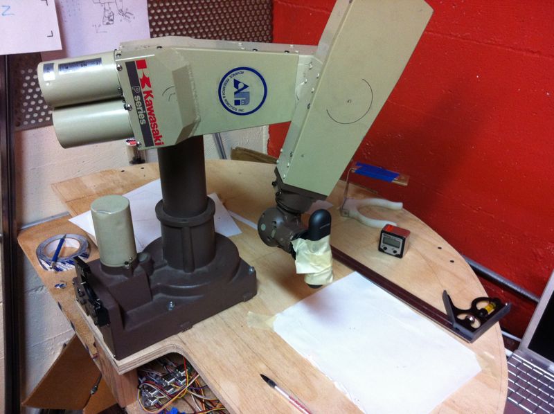
It turned out there were a couple of issues translating from the motor encoder positions to joint angles. Initially, I tried to just open up the arm and count teeth on the gears to calculate the gear ratio. That proved difficult, in part because most of the joints have some gears that are hidden (inside castings or behind other parts), and I didn't want to do any damage by pulling gears off shafts, etc. Ultimately, on the advice of a friend, I used this digital angle gauge to calibrate the arm, and it worked perfectly.
The other thing I discovered was that the wrist motors are actually coupled. If you move the motor for joint 4, it also effects the angle of joints 5 & 6, and joint 5 feeds forward to joint 6. So I calibrated out those connections as well, and added code to account for it when translating between motor encoder counts and joint angles. So finally, I had a way to translate between encoder counts, joint angles and Cartesian space.
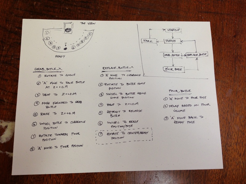
In addition to the control code, I also created a scripting language I could use to create and store paths for the robot arm to traverse. So later on, once I'd built the table, I created a script to grab each bottle, and another set of scripts to return them to the holders. The encoders in the arm are quite accurate, and so each position along each path is fairly repeatable, down to about a millimeter. I spent quite a bit of time tuning the paths to make sure each bottle was captured and then replaced by the gripper, and still have a little bit of that tuning left to do.
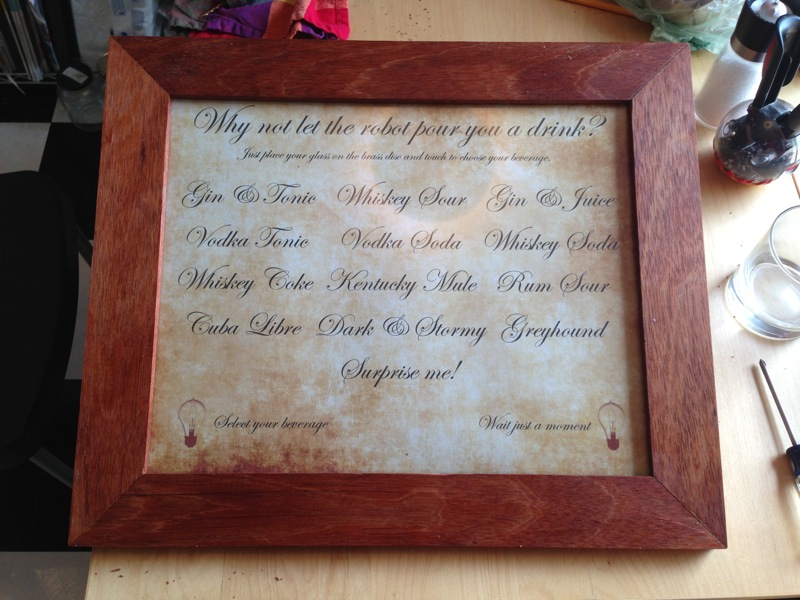
Fairly late in the game, I decided exactly how the users of the system would actually select a drink. From a prior consulting job, I had a 15" touch panel — the glass that goes on the front of a touch screen, but not the LCD monitor itself. I was pretty tickled by the idea of just putting a piece of paper behind that touch panel and having a static touch "screen" that looked like a picture in a frame.
It didn't take too long to figure out how to connect the touch panel to the computer via a second USB-to-serial converter and an easy Perl program to parse the data packets. It also became clear that it would be helpful to have a little bit of feedback on the menu: "I'm ready to make the next drink" and "I'm busy." I wound up using another two of the GPIOs on the USB-to-I2C board to control two LEDs that wound up shining through the menu.
The final programming task was to create a program that read input from the touch screen, translated that into a drink selection, and sent the appropriate set of commands (by reading in scripts) to the arm.
Cabinet Construction & Woodworking
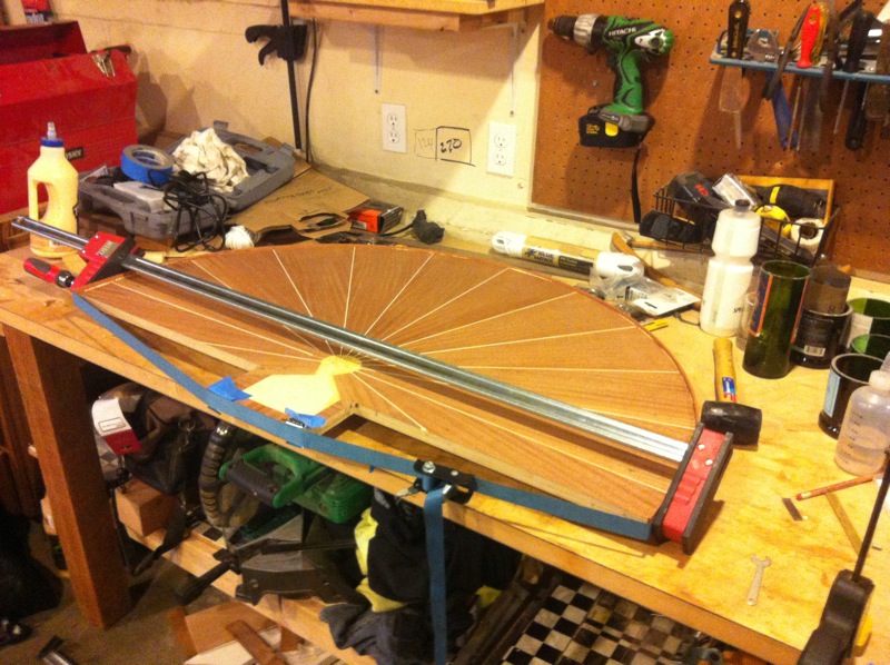
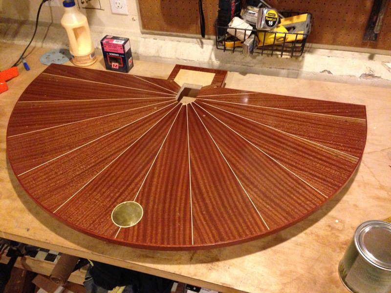
Once I had the software working on the prototype table, I felt confident moving forward with the final enclosure, a custom-designed veneered demilune table that presents the bottles and arm as well as houses the electronics.
With this project in mind, I bought some ribbon sapele veneer on sale at Woodcraft a while back, and I picked up a nicer piece of ¾" plywood to use as a substrate. In a previous project, I'd used regular, yellow wood glue and an iron to essentially make my own iron-on veneer, and I decided to do that again.
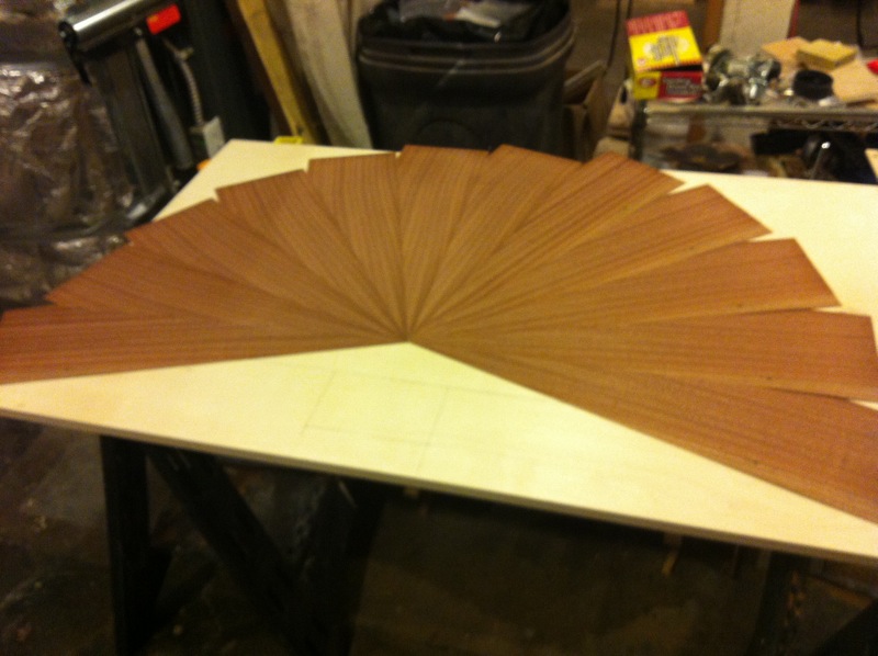
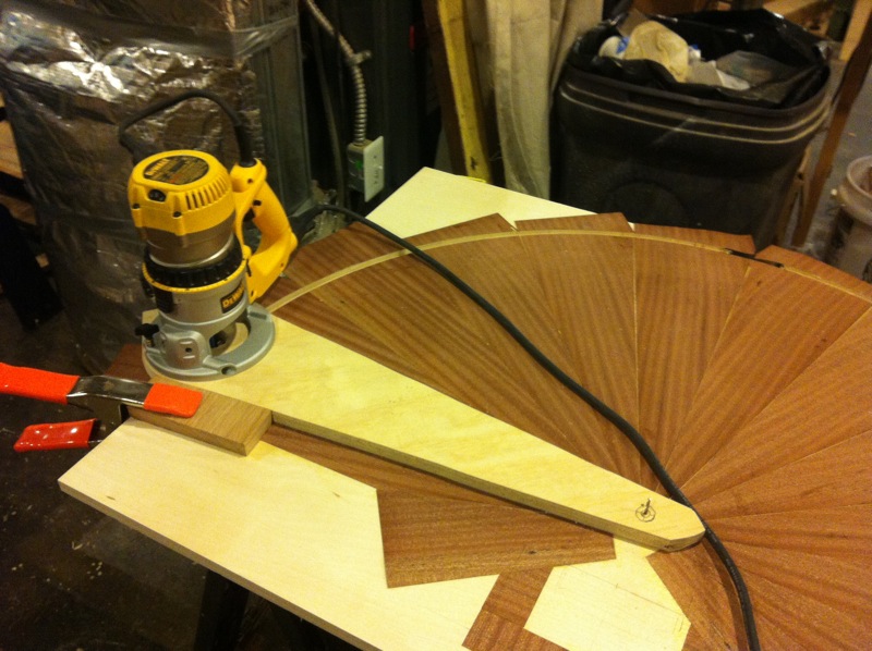
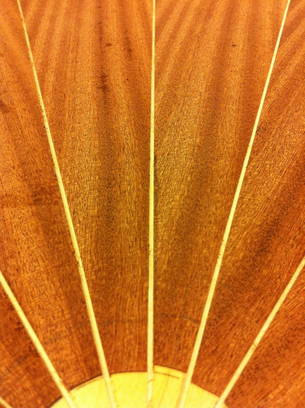
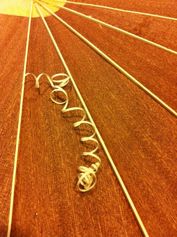
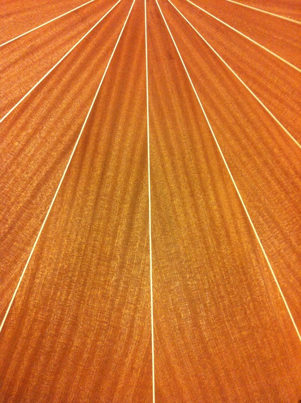
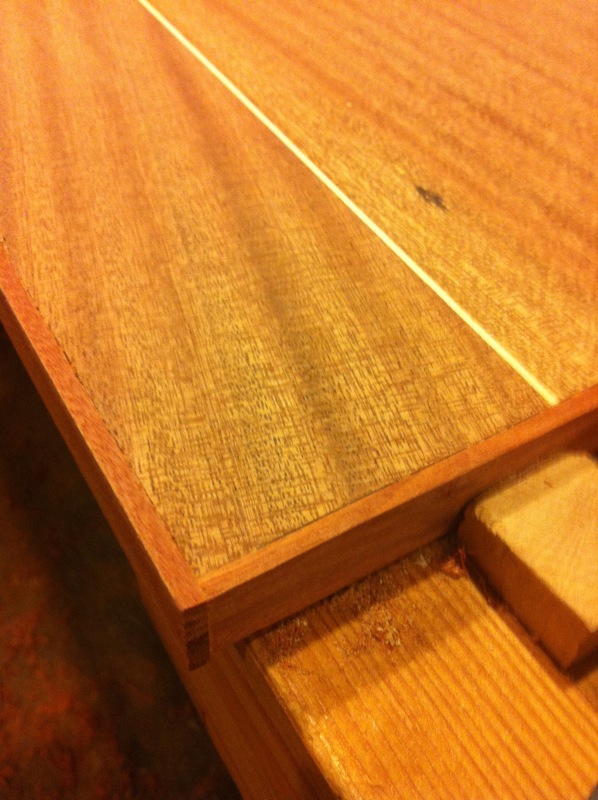
Using a veneer saw, I cut a bunch of wedges of veneer, coated them (and the substrate) with yellow glue, and let them dry for a couple hours. After ironing down the veneer, I used a router (in a compass jig) to trim the tabletop to the final shape. With the veneer in place, I then used a dremel tool (with a custom-made router base) to cut shallow grooves at the joints of the veneer wedges — these grooves would later be filled with holly wood (a very bright white) strips. I used a block plane and then a scraper to bring the holly strips down to flush with the veneer.
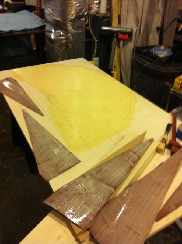
A little side note here — if I had this to do again, I wouldn't use the glue/iron combo. It's difficult to get complete adhesion, and I already have a couple of spots where the veneer is bubbling up. On the plus side, the glue up was fairly quick, and positioning the veneer during glue up was easy, but ultimately, I'd trade slower (and possibly more finicky) assembly for peace of mind and permanent adhesion.
I ripped a few thin (maybe 1/8" thick?) pieces of sapele to act as edge-banding on the outside edges of the table top, and I glued these in place directly.
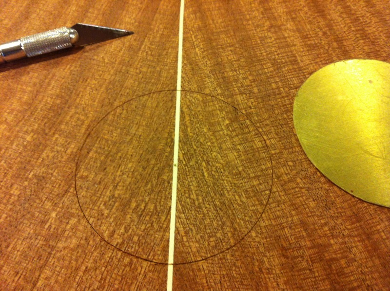
I also inlaid a brass disc to indicate where people should put their glass during use — essentially a target. This (plus some finishing) completed the table top.
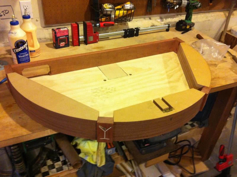
The base of the table (where the electronics are housed) is even less traditionally constructed. I built a band saw jig to cut a series of arcs out of MDF, and then stacked these to make curved walls.
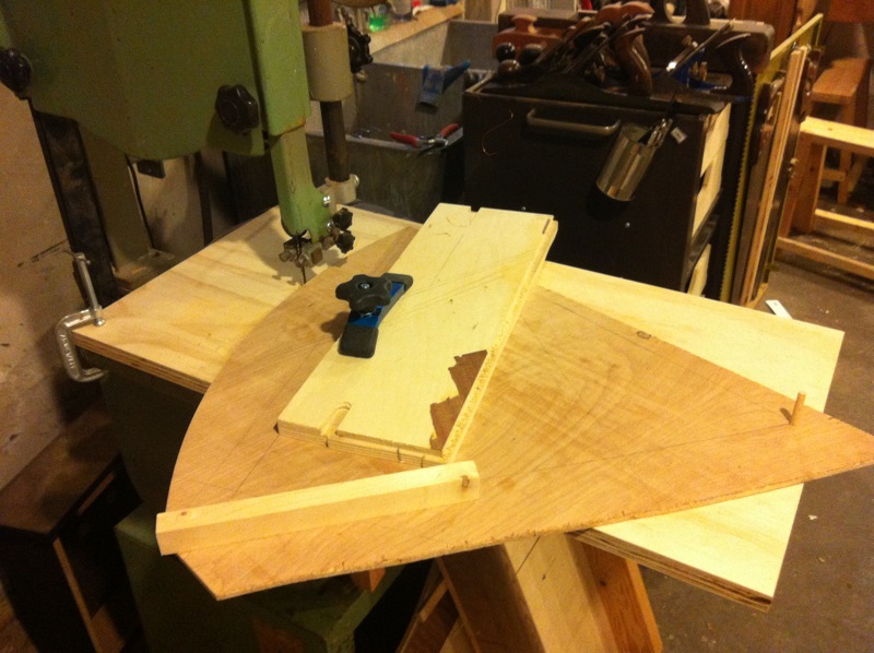
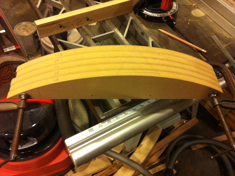
I used the cut-off pieces of MDF (again, stacked and glued) as cauls to glue and clamp veneer onto that curved surface.
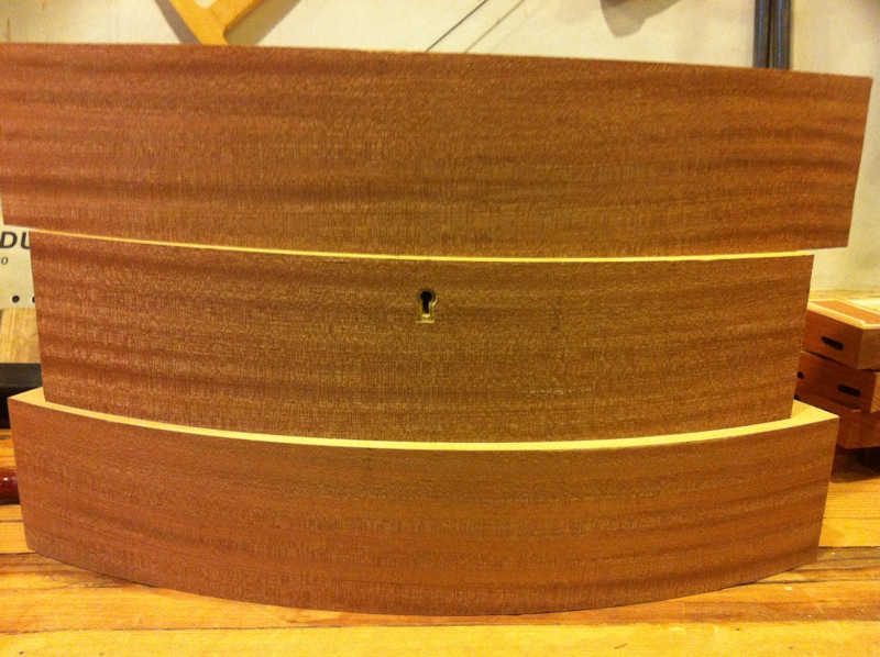
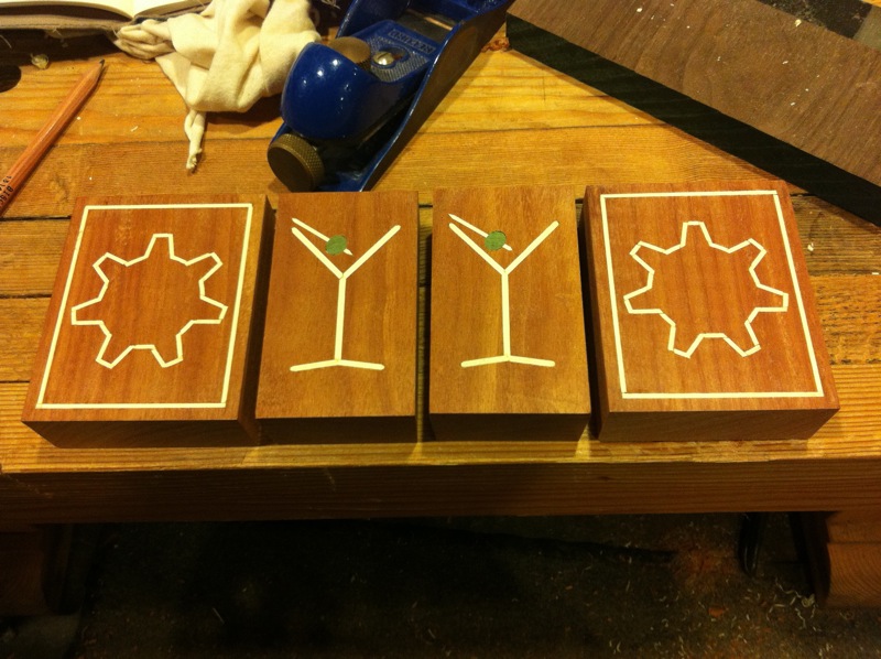
Those veneered, curved sections are separated by small blocks of solid sapele, joined by way of dominos — thank you, Avi, for the loan of the domino joiner. And thank you, too, for use of your awesome CNC mill to cut these great designs in those wood blocks. Once again, I used holly strips to provide a contrasting color for the inlay.
The back of the enclosure is made from a solid sapele board. You might be thinking, by now, that this base section is getting heavy, and you'd be right, but that's not by accident. The arm can actually generate significant forces when it's starting and stopping, so I wanted a base with enough mass to damp those forces. This combo of MDF and sapele definitely works, though it does make the whole thing kind of a beast to move. (You can see the liquid in the bottles sloshing around in some of the videos — the table I had the whole bartender sitting on at the Pi(e) Party was on casters, and even with those locked, the table could move back and forth a bit, hence the sloshing.)
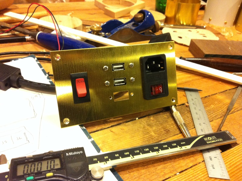
I cut an opening on the back and made a custom brass plate to accomodate all the cables and cords and signals that had to enter/exit the enclosure:
- power in, with fused on/off switch
- a couple USB connections
- video (VGA)
- a run/stop switch
- an extra set of wires to control status LEDs on the menu (added late in the game)
The top is connected to the enclosure via two long piano hinges in the back, and can be latched/locked in the front (via a cabinet lock).
I put one coat of Danish oil on all the wood parts, let it dry thoroughly, and then applied 4 or 5 coats of polyurethane finish.
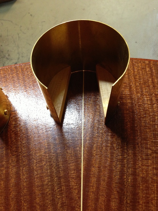
Once again, thanks are due to Avi and his awesome shop, where I used his shear and slip roller setup to make the brass bottle holders. These are screwed into small maple blocks that raise the bottom of the bottle a bit off the table top, allowing the metal part of the gripper to slide underneath.
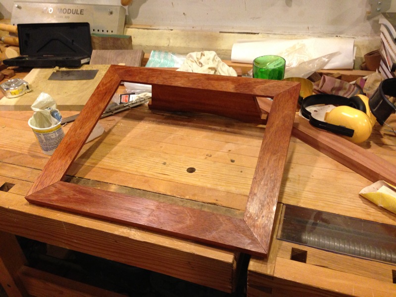
With Jared's help, I also built a picture frame to hold the touch panel, and designed some artwork to put behind the touch panel.
After some last minute tweaks, the arm was ready for primetime!
Pictures & Videos
Check out the full page of robot bartender photos and videos, both in-progress and of the finished product, here.
There are also some great pics from the Pi(e) Party where the bartender made its debut here — thanks, George!
What's Next?
In short, I don't really know.
There are still some things I'd like to tune up with the bartender — it occasionally misses when replacing a bottle, the pouring path could be smoother, the LEDs on the menu could be brighter, and so on. If I wanted to bite off a bigger chunk, I might think again about using my own PCB / motor control circuitry, rebuild the touch screen menu with a separate microprocessor, or possibly rebuild the table top (to add decorations and eliminate the bubbling in the veneer).
I was sad that we were away this year during BarBot, so maybe I'll go next year?
And it turns out ther are other things that you can do with a robot arm, especially a working one...
Acknowledgements
Obviously, this isn't the kind of project that gets done solo — there are a host of people who contributed in one way or another, and I wanted to make sure they were publicly acknowledged. I couldn't have done it without:
- My brother Matt. Pro tip: if you're trying to make something robotic, it is a huge leg up to have a family member who's a professor of robotics, and a good one, to boot.
- My girlfriend Dina, for more than tolerating the presence of a robot arm in our living room for a while, but supporting my dream of turning into a bartender, and choosing the soundtrack for its debut.
- Avi, for a really well-outfitted shop (including the CNC), as well as lots of design consultations.
- Jared, for not only some 3d printing (the gripper), but more design consultation, some graphics help, and lots more.
- ALTSpace, where I've had a desk for the better part of a year. It's a well-outfitted maker-space with supportive members, and was a great spot for doing the last bits of development.
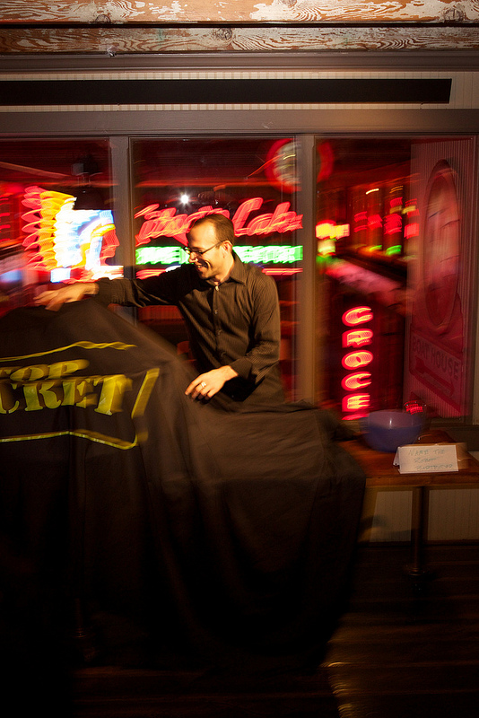
- Brian at Synapse, for a lot of electrical debugging help, and also the "TOP SECRET" drape.
- Laura, for driving me through rush hour traffic in Boston one morning before work to pick up the arm at Northeastern one fateful day in 2002. I hope I bought you breakfast, at least, and I certainly owe you a robot-poured drink!
- A whole lotta friends (and some strangers) who believed I could actually make this happen. Even though it took a while, I did it, and I appreciate the support!